AKD
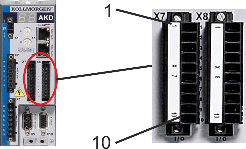
Standard digital and analog I/O signals are connected to X7 and X8.
|
AKD
|
|---|
|
|
|
Conn. |
Pin |
Signal |
Abbreviation |
|
|---|---|---|---|---|
|
X7 |
1 |
Digital Common X7 |
DCOM7 |
Common line for |
|
X7 |
2 |
Digital Input 7 |
DIGITAL-IN 7 |
Programmable |
|
X7 |
3 |
Digital Input 4 |
DIGITAL-IN 4 |
Programmable |
|
X7 |
4 |
Digital Input 3 |
DIGITAL-IN 3 |
Programmable |
|
X7 |
5 |
Digital Output 2- |
DIGITAL-OUT2- |
Programmable |
|
X7 |
6 |
Digital Output 2+ |
DIGITAL-OUT2+ |
Programmable |
|
X7 |
7 |
Digital Output 1- |
DIGITAL-OUT1- |
Programmable |
|
X7 |
8 |
Digital Output 1+ |
DIGITAL-OUT1+ |
Programmable |
|
X7 |
9 |
Digital Input 2 |
DIGITAL-IN 2 |
Programmable,fast |
|
X7 |
10 |
Digital Input 1 |
DIGITAL-IN 1 |
Programmable,fast |
|
|
||||
|
X8 |
1 |
Fault Relay Output |
Fault Relay Output |
Fault Relay Output |
|
X8 |
2 |
Fault Relay Output |
Fault Relay Output |
Fault Relay Output |
|
X8 |
3 |
Digital Common X8 |
DCOM8 |
Common line for |
|
X8 |
4 |
Digital Input 8 |
DIGITAL-IN 8 |
Output stage enable, |
|
X8 |
5 |
Digital Input 6 |
DIGITAL-IN 6 |
Programmable |
|
X8 |
6 |
Digital Input 5 |
DIGITAL-IN 5 |
Programmable |
|
X8 |
7 |
Analog Ground |
AGND |
Analog GND |
|
X8 |
8 |
Analog Output + |
Analog-Out |
Actual velocity voltageVoltage proportional to the actual velocity |
|
X8 |
9 |
Analog Input - |
Analog-In- |
Velocity set point |
|
X8 |
10 |
Analog Input + |
Analog-In+ |
|
Digital common lines for X7 and X8 are not common to each other.
The DCOMx line should be connected to the 0V of the I/O supply when using sensors of type "Source" with digital inputs.
The DCOMx line should be connected to the 24V of the I/O supply when using sensors of type "Sink" with digital inputs.
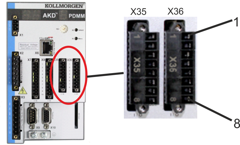
PDMM offers two additional connectors X35 and X36 for digital I/O signals.
|
AKD-M |
|---|
|
|
|
Conn. |
Pin |
Signal |
Abbreviation |
Function |
|---|---|---|---|---|
|
X35 |
1 |
Digital Common X35 |
DCOM35 |
Common line for |
|
X35 |
2 |
Digital Input 21 |
DIGITAL-IN 21 |
Programmable |
|
X35 |
3 |
Digital Input 22 |
DIGITAL-IN 22 |
Programmable |
|
X35 |
4 |
Digital Input 23 |
DIGITAL-IN 23 |
Programmable |
|
X35 |
5 |
n.c. |
n.c. |
- |
|
X35 |
6 |
n.c. |
n.c. |
- |
|
X35 |
7 |
Digital Output 21- |
DIGITAL-OUT21- |
Programmable |
|
X35 |
8 |
Digital Output 21+ |
DIGITAL-OUT21+ |
Programmable |
|
|
||||
|
X36 |
1 |
Digital Common X36 |
DCOM36 |
Common line for |
|
X36 |
2 |
Digital Input 24 |
DIGITAL-IN 24 |
Programmable |
|
X36 |
3 |
Digital Input 25 |
DIGITAL-IN 25 |
Programmable |
|
X36 |
4 |
Digital Input 26 |
DIGITAL-IN 26 |
Programmable |
|
X36 |
5 |
n.c. |
n.c. |
- |
|
X36 |
6 |
n.c. |
n.c. |
- |
|
X36 |
7 |
Digital Output 22- |
DIGITAL-OUT22- |
Programmable |
|
X36 |
8 |
Digital Output 22+ |
DIGITAL-OUT22+ |
Programmable |
Digital common lines for X35 and X36 are not common to each other.
The DCOMx line should be connected to the 0V of the I/O supply when using sensors of type "Source" with digital inputs.
The DCOMx line should be connected to the 24V of the I/O supply when using sensors of type "Sink" with digital inputs.
|
Stay Connected with Kollmorgen       
|
Copyright © 2015 Kollmorgen™ |

|